 Schedule Service

Integrating Legacy PLCs with Modern HMI and SCADA Systems
Modernize Monitoring Without Losing Field-Proven Hardware
The Business Case for Bridging Old and New
Industrial facilities across the Gulf Coast region continue operating programmable logic controllers that were installed decades ago. These systems control critical processes in refineries, chemical plants, and oil and gas operations throughout Louisiana and Texas. The hardware remains mechanically sound, the logic has been debugged over years of production, and operators understand exactly how each sequence executes. Replacing functioning equipment purely for the sake of modernization rarely makes financial sense when production schedules and capital budgets are already stretched.
Modern HMI solutions and SCADA systems deliver capabilities that older interfaces cannot match. Real-time data visualization, remote access for engineers working from multiple sites, predictive analytics that flag potential failures before they cause downtime, and integration with enterprise systems that track maintenance schedules and inventory all depend on continuous, structured data flows. The challenge is bridging the gap between controllers that were designed for isolated, hardwired operation and software platforms built around networked, digital communication protocols.
Three concerns dominate conversations when facility managers consider integration projects. First, the risk of disrupting production during implementation can outweigh the perceived benefits, particularly in continuous-process industries where even brief interruptions cascade into significant financial losses. Second, many aging controllers use proprietary communication methods or serial protocols that modern Ethernet-based systems do not natively support. Third, the institutional knowledge required to modify ladder logic or reconfigure decades-old hardware often resides with a small group of senior technicians who are understandably cautious about changes that might introduce instability. Addressing these concerns requires a structured approach that minimizes risk, leverages existing investments, and delivers measurable improvements in visibility and operational efficiency.
Diagnostic Steps Before You Wire Anything
Every successful integration begins with a detailed inventory of existing hardware and software. Document the make, model, and firmware version of each controller, along with the physical location and the process it manages. Record the current communication interfaces available on each unit, whether serial ports like RS-232 or RS-485, or older Ethernet modules that may support limited protocols. In facilities spread across multiple acres, such as upstream production sites common in the Permian Basin and East Texas fields, this inventory phase often reveals controllers that were installed by different contractors over the years, resulting in a mix of brands and configurations that must be reconciled before any integration work begins.
Next, map the data flows that the new HMI programming software will require. Identify which process variables need real-time updates, which alarms must be forwarded to central monitoring, and which historical trends are essential for production optimization. This step distinguishes between data that operators actively use for decision-making and data that simply fills screen space. In one Louisiana chemical plant deployment, reducing the tag count by 40 percent during the planning phase eliminated unnecessary polling cycles and allowed the communication infrastructure to handle the remaining tags with sub-second update rates, improving both performance and operator confidence.
Evaluate the existing network infrastructure, or lack thereof. Many legacy installations rely on point-to-point wiring with no networking between controllers. Adding a digital communication layer requires either retrofitting Ethernet switches and cabling or deploying wireless systems where trenching and conduit installation would be prohibitively expensive. In remote wellhead monitoring scenarios, industrial wireless control often proves more practical than running fiber optic cable across lease roads and waterways. The assessment should quantify the costs and timelines for each approach, factoring in the environmental conditions, distances, and the level of data security required for the application.
Middleware, Gateways, and Protocol Translation
Protocol translation gateways serve as the technical bridge between legacy serial communications and modern Ethernet-based networks. These devices accept connections from older controllers using Modbus RTU, DF1, or proprietary serial formats, then repackage the data into Modbus TCP, EtherNet/IP, or OPC-UA frames that contemporary SCADA software can consume. Selecting the correct gateway depends on the specific controller family and the target SCADA platform. Some gateways handle only a single protocol pair, while others support multiple simultaneous translations, allowing a single device to serve several controllers with different communication methods.
OPC-UA has emerged as the preferred standard for interoperability in industrial automation. Unlike older OPC-DA implementations that required Windows-based servers and DCOM configuration, OPC-UA operates platform-independently and includes built-in security features such as encryption and user authentication. When integrating controllers into a PLC control system that will be accessed remotely, OPC-UA provides the data model and transport layer that both protects sensitive process information and enables secure website monitoring from any location with network access. This capability has become essential for facilities that operate across multiple sites and require centralized oversight without maintaining dedicated control rooms at each location.
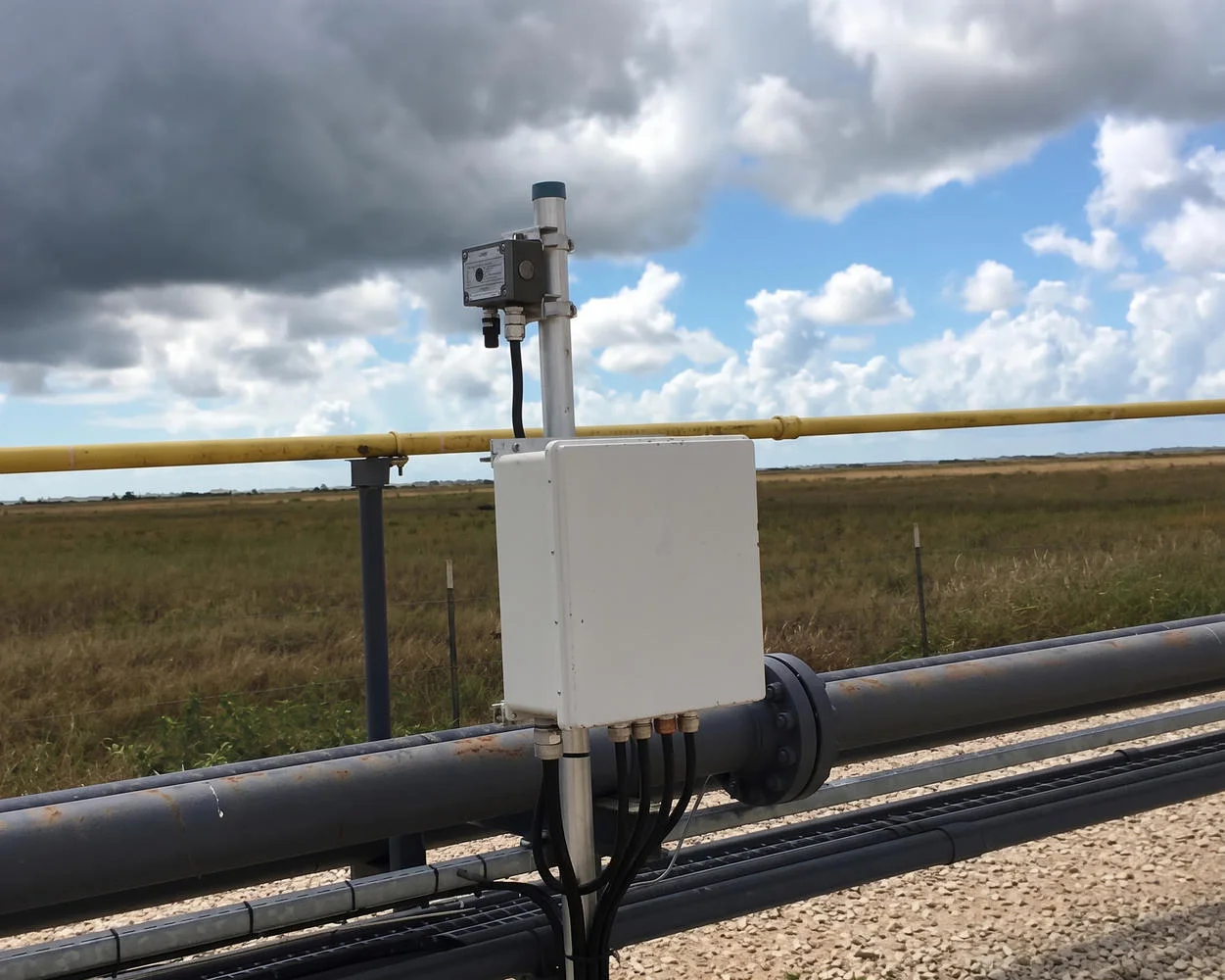
In distributed applications such as pipeline monitoring, tank farms, or offshore platforms where controllers are separated by significant distances, industrial wireless control systems eliminate the need for extensive cabling. Licensed industrial bands offer interference-resistant communication with ranges measured in miles, while mesh networking topologies provide redundancy if a single radio link fails. Integrating wireless nodes into a SCADA environment requires careful attention to update rates and latency. While a wired Ethernet connection might deliver tag updates every 100 milliseconds, a wireless link traversing multiple hops may require 500 milliseconds or more. Understanding these timing characteristics during the design phase prevents surprises when the system goes live and ensures that alarm response times meet operational requirements.
The choice of protocol and hardware also determines how easily the system can scale in the future. A gateway-based architecture allows incremental expansion without replacing existing controllers, while a SCADA platform that supports multiple protocols natively simplifies the addition of new devices as production lines grow or processes change. In Gulf Coast facilities where seasonal demand shifts and regulatory requirements frequently evolve, this flexibility protects the initial integration investment and avoids vendor lock-in that could limit future options.
Continuous Monitoring and Predictive Upkeep
Pilot testing on non-critical systems reduces risk and builds operator confidence. Select a controller that manages a process with built-in redundancy or one that can be taken offline during a planned maintenance window. Install the gateway, configure the SCADA tags, and verify that data updates match the expected values by comparing SCADA screen readings with the physical field instruments and the controller’s local display. This side-by-side validation confirms that communication is stable, tag scaling is correct, and alarm thresholds trigger appropriately before expanding the integration to controllers that cannot tolerate downtime.
In one South Texas gas processing facility, the team ran a parallel SCADA system for two weeks alongside the existing panel-mounted HMI before switching operational control. Operators used the new interface to monitor trends and confirm alarm sequences, while still relying on the legacy screens for process adjustments. This overlap period identified several tag mapping errors and a polling rate that caused occasional timeouts during peak load conditions. Correcting these issues before full cutover prevented production interruptions and demonstrated that the new system could be trusted under real-world conditions.
Data integrity verification extends beyond simple tag value checks. Test historical trending by logging data over several days and comparing the SCADA archive against known process events. Introduce simulated faults, such as disconnecting a field device or forcing a controller input, to confirm that alarms propagate correctly and that remote monitoring dashboards reflect the change within acceptable timeframes. Document the behavior under network stress, such as during a temporary wireless link outage or a switch reboot, to ensure the system recovers gracefully without data loss or erratic tag updates that could mislead operators.
Training must address both the new interface and the underlying system architecture. Operators need to understand which data comes directly from the controller and which values are calculated within the SCADA platform. Maintenance technicians require documentation of the communication pathways so they can troubleshoot connectivity issues without escalating every minor fault. In facilities where staff turnover is common, clear documentation and hands-on training sessions reduce the learning curve and ensure that the PLC maintenance practices adapt to the expanded monitoring capabilities. When everyone understands how the pieces fit together, the system becomes a tool that enhances daily operations rather than a source of confusion and support calls.
When to Maintain, When to Replace
Integration is not a destination but the beginning of a continuous improvement cycle. After deployment, establish a baseline for data quality and system performance. Compare the values displayed on the modern HMI against local field instruments and the legacy controller displays to confirm accuracy. Document any discrepancies and adjust scaling factors, offset values, or data mapping configurations in the gateway or HMI software until the displayed values match reality within acceptable tolerances.
Schedule regular inspections of the communication infrastructure. Check cable terminations at serial-to-Ethernet converters, verify network switch uptime logs, and monitor error counters in gateway diagnostics. Many facilities in Houston and Midland operate in environments where temperature swings, vibration, and humidity can degrade connections over time. Monthly visual checks and quarterly diagnostic scans prevent small issues from escalating into unplanned outages.
Leverage the new data visibility to shift from reactive repairs to predictive upkeep. Configure trending dashboards that track cycle counts, run times, and alarm frequencies for each controller. Rising alarm rates or increasing response times often indicate memory degradation, power supply drift, or I/O card failures before they cause a shutdown. PLC control systems benefit from this early-warning approach, allowing teams to stage replacement modules and schedule interventions during planned maintenance windows rather than emergency callouts.
As operational needs grow, the integrated architecture provides a foundation for expansion. Adding new controllers to the network becomes simpler once communication standards and gateway configurations are in place. Facilities can extend digital communication to remote sites using wireless systems, stream process data to cloud-based historians for long-term analysis, or enable web-based monitoring that gives management real-time visibility from any location. The investment in integration pays dividends by making future upgrades incremental rather than disruptive, preserving both the reliability of legacy hardware and the agility that modern platforms deliver.